
Creating Schematics for the Site
There were two hurdles impeding me from finishing my writeup of the Telemetry demo: how to present the various code examples in a visibly-pleasing manner and how to easily draw schematics that are accurate and communicate clearly.
The first problem will be solved later using a syntax mark-up module, the second is tonight's topic.
I saw images like the one below and wanted to make something similar.
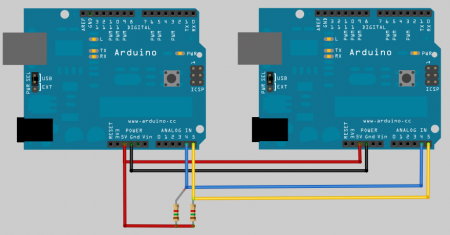
It took a bit of creative Googling and reading through forums but eventually I found a blog entry that pointed me in the right direction here: http://www.gadgetsappshacks.com/2010/01/drawing-arduino-circuit-diagram.html
Here the author describes using fritzing to create quick schematics to record his work. I need to do something similar as I tear down the Telemetry demo kit so I can document it properly.
I downloaded Fritzing, and unzipped the file to a folder on my desktop. I like that I don't need administrative privileges on my system to install and run the program. Just go into the new directory, double click on the fritzing icon and you're presented with a breadboard view. You can pull items and place them on the breadboard, or click on the schematic tab and work with it that way. Just drag parts over from the part selector, drop them on the view, and if you want to connect them, just draw a line between the elements you want to connect.
Just a little poking and you get something like this:
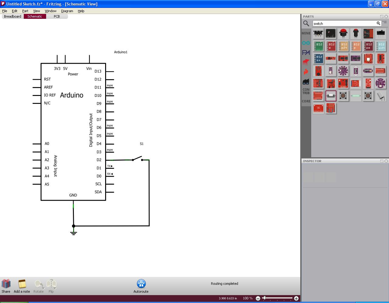
Here you can see a partial circuit, note how I searched for "switch" in the part selector. There are lots of other part libraries available to download from the community.
Now I can get to tearing that old box apart and recording how we put it together...
- Log in to post comments